

Design Language
of CNC
Jewelry Machine
Designing the industrial form language of the AZF CNC jewelry machine with an approach toward improving user experience and strengthening brand identity.

Central Tehran Branch (Sohanak)
PRECISION.
CRAFT.
IDENTITY.

Jewelry CNC machines exist at the intersection of digital manufacturing, precision engineering and traditional craftsmanship.
This project studies the current AZF CNC product family and develops a coherent industrial form language that improves usability, perceived quality and brand recognition.
The objective is not limited to styling the exterior enclosure. The design process considers operator interaction, access, maintenance, manufacturing constraints and the visual character of the jewelry industry.
CONFIDENCE
The machine must visually communicate accuracy, structural stability and controlled mechanical performance.
CHARACTER
Form, material and finishing should reflect the precision, delicacy and value associated with jewelry production.
AZF DNA
A consistent design language should make future AZF products recognizable as members of one professional machine family.
UNDERSTANDING
THE DESIGN
CHALLENGE.
Jewelry CNC machines are commonly developed around mechanical performance, accuracy and production requirements.
Although these factors are essential, industrial design, operator experience and visual identity are often treated as secondary considerations.
This creates products that may perform effectively but appear visually complex, difficult to approach and disconnected from the refined character of jewelry manufacturing.

LIMITED PRODUCT
RECOGNITION
The current enclosure does not establish a strong and immediately recognizable AZF product identity.
COMPLEX USER
EXPERIENCE
Access points, controls and operational zones require clearer visual hierarchy and more intuitive interaction.
WEAK PREMIUM
CHARACTER
The visual language does not fully reflect the precision, craftsmanship and value associated with jewelry production.
UNCLEAR SERVICE
ACCESS
Maintenance areas and removable components need clearer separation and more efficient technical access.
PERFORMANCE
IS NOT ENOUGH.
The redesign must preserve the machine's technical performance while transforming its exterior architecture, usability and visual communication.
Every design decision must balance engineering requirements, operator needs, manufacturing feasibility and brand identity.
PERFORMANCE
Accuracy, stability, protection and machine performance must remain uncompromised.
INTERACTION
The machine should become easier to understand, access, operate and maintain.
AZF DNA
The product should communicate premium engineering, precision and professional confidence.
RESEARCH
FRAME
WORK.
This framework organizes the design research process before entering detailed product analysis. It connects machine observation, user needs, benchmark references, production limitations and brand direction into one structured industrial design method.
Context Mapping
Defines the machine environment, operator workflow and product position.
Product Analysis
Studies enclosure structure, access zones, proportions and visual hierarchy.
User Observation
Tracks operator touchpoints, visibility, service access and control flow.
Benchmark Study
Compares CNC references through premium cues and industrial form logic.
Manufacturing Logic
Aligns design intent with sheet metal, assembly, panels and constraints.
Design Synthesis
Transforms research into form language, CMF direction and AZF identity.
PRODUCT
ANALYSIS
Investigates machine proportions, surfaces, access areas, visibility and technical enclosure logic.
TAG / PA-01USER
OBSERVATION
Studies operator behavior, daily workflow, interaction points, service actions and ergonomic needs.
TAG / UO-02BENCHMARK
STUDY
Compares competitive CNC products through structure, detail quality, lighting and premium identity.
TAG / BS-03DESIGN
LANGUAGE
Defines the visual DNA, material direction, surface rhythm and recognizable AZF machine character.
TAG / DL-04CURRENT
PRODUCT
SCAN

Upper housing defines the main industrial silhouette.
Large front volume needs stronger hierarchy and refinement.
Operator approach area requires clearer interaction priority.
Service panels can communicate modularity more clearly.
Primary opening should feel safer, cleaner and more premium.
Interface area needs stronger visibility and ergonomic logic.
Lower body anchors the machine but appears visually heavy.
Technical access should be separated from daily operation.
Machine presence must balance stability with visual precision.
Vertical and horizontal masses need a unified design rhythm.
Current surface lacks a dedicated AZF identity zone.
Future design can use controlled light as a premium signal.
MARKET
REFERENCE
MAP
Clean enclosure architecture, simplified operator-facing surfaces and refined proportions establish a premium industrial impression.
Recognizable product family language, clear service zones and robust visual confidence define the machine as a reliable production tool.
Jewelry-specific precision, compact production fit and premium redesign potential create a clear opportunity for AZF differentiation.
AZF
ADVANTAGE
DESIGN
EVOLUTION
Functional enclosure and mechanical protection.
Operator zones, safety perception and service hierarchy.
Precision through form, material and light.
OPERATOR
JOURNEY
MAP
FLOWHuman Centered
Loading
Material placement needs clearer access and reduced operator hesitation.
Operation
The control zone needs calmer hierarchy and stronger legibility.
Monitoring
Process status and visibility should be easier to read at a glance.
Maintenance
Service actions need dedicated panels and faster technical access.
Cleaning
Residue removal should feel organized and less time-consuming.
Emergency
Critical actions must be visually immediate and physically reachable.
REDUCES
STRESS
The redesign must make the operator feel confident before, during and after machine operation.
Too many surfaces compete for attention around the operating zone.
Daily operation and service access are not clearly separated.
The user experience does not yet match jewelry-level precision.
FUTURE
AZF
IDENTITY
AZFProduct DNA
Ergonomics
Clarify operation zones and daily interaction.
Manufacturing
Use feasible sheet-metal logic and controlled seams.
Modularity
Create panel systems for service and future products.
Brand Language
Build recognizable AZF proportions and detailing.
Maintenance
Separate operator access from technical service.
Safety
Improve perceived protection and clear controls.
Future Expansion
Prepare the design system for future AZF machines.
CONCEPT
EXPLORATION
BOARD
PRIMARY
VOLUME

First exploration searches for a stronger silhouette and cleaner machine body.
REFINED
PROFILE

Second direction improves balance, panel rhythm and premium front character.
FAMILY
DIRECTION
The final exploration combines calm precision with modular service logic.
NEW
PRODUCT
DIRECTION
The concept development phase converts the sketch exploration into a controlled industrial design language for the future AZF CNC family.
Form
Definition
Establish the primary volume, front face identity and balanced industrial proportions.
System
Integration
Connect operation, service, safety and manufacturing logic into one structure.
Premium
Refinement
Apply controlled details, lighting, CMF and brand cues to create AZF identity.
CALM
TECHNICAL
POWER
The concept moves away from visual complexity and toward a premium CNC architecture: strong base, clean enclosure, visible operator zones, precise seams and a jewelry-level metallic accent system.
Main enclosure with low-gloss industrial depth.
Signature detail for key visual lines.
Functional technical parts and references.
Process visibility with premium character.
FROM SKETCH
TO CONCEPT


Machine
Mass
Initial direction studies the AZF product volume as a controlled industrial object.
Refined
Surface
Visual complexity is reduced through clearer panel rhythm and sharper edges.
Premium
Precision
Form development moves toward a confident, minimal and jewelry-grade CNC identity.
ENGINEERING
THE FORM
Control
Front-view proportions are translated into cleaner CAD surface logic.
Strategy
Operation, maintenance and brand surfaces become separate design layers.
Build
The design remains grounded in sheet-metal production and service access.
Current machine volume and footprint are measured.
Surface hierarchy and access zones are clarified.
Final line logic defines premium proportions.
FINAL
AZF
DESIGN

CMF
DESIGN
BOARD

Black Matte
Metal
Primary exterior language with low reflectivity and deep industrial presence.
Powder
Coating
Durable production finish suitable for high-use CNC environments.
Glass
Surface
Controlled process visibility with a premium dark technical character.
Brushed
Steel
Functional areas communicate accuracy, strength and service trust.
Aluminium
Detail
Lightweight technical surfaces for trims, handles and precision interfaces.
AZF
Gold
Signature identity color used only for intentional highlights and visual guidance.
FROM SHEET
TO MACHINE

Laser
Cutting
Accurate sheet profiles define panels and openings.
Bending
Controlled folds create clean surfaces and stiffness.
Welding
Hidden structure connects body panels and frame.
Painting
Matte powder coating adds durability and depth.
Assembly
Modules, windows, trims and panels are integrated.
Quality
Control
Surface finish, panel fit and access are verified.
FOR
PRODUCTION
The final concept respects CNC machine construction while improving surface quality, service clarity and brand consistency.
Large surfaces are divided according to production and service logic.
Join lines become part of the visual architecture.
CMF choices support consistent production quality.
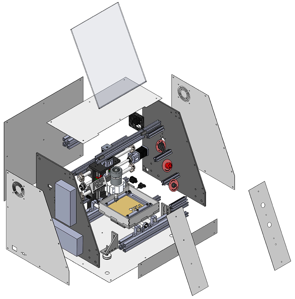
ASSEMBLY
LAYERS

Top geometry separated from the real isometric machine photo.
Large body volume isolated as structural architecture.
Operator visibility zone is treated as its own component.
Side area becomes a technical maintenance layer.
Lower body grounds the machine and supports assembly.
PROJECT
PROCESS.
Research
Context and user study.
Analysis
Product and benchmark scan.
Strategy
Future AZF design DNA.
Sketches
Concept exploration.
Development
CAD and CMF refinement.
Final Design
Premium CNC direction.
DESIGN
TRANSFORMATION.

From generic volume to controlled premium geometry.
Clearer operator surface and improved access logic.
Defined service areas and more readable panel strategy.
Recognizable AZF character through CMF and front architecture.
VISUAL
DNA.
Sharp Geometry
Precision
Minimalism
Industrial Identity
Structural Balance
Premium Appearance
FUTURE AZF
PRODUCT FAMILY
It should define an entire family.
Early sketches tested how aggressive or calm the AZF machine should feel.
The design shifts toward a clearer interface and balanced product volume.
The next phase combines refined massing with modular service logic.